In a matrix format LEDs are arranged in rows and columns. You can also think of them as y and x coordinates. Lets assume we have 4x4 matrix. Rows would be marked from A to D and columns from 1 to 4. Now we can address each LED by row and column. Top left led would be (A,1). Bottom down led would be (D,4).
Led matrices come in two flavors. Common-row anode (left) and common-row cathode (right).
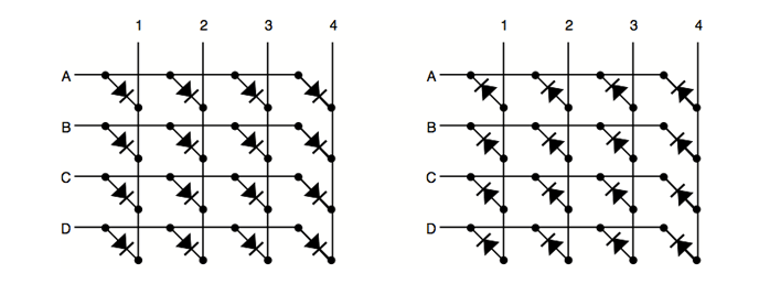
Figure above shows the different configurations. The difference between these two configurations is how you lit a led. With common-row anode current sources (positive voltage) are attached to rows A..D and currents sinks (negative voltage, ground) to columns 1..4. With common-row cathode current sinks are attached to rows A..D and currents sources to columns 1..4.
For example. To light bottom down led (D,4) of common cathode matrix you would feed positive voltage to column 4 and connect row D to ground. For sake of clarity I will using common-row cathode in examples for the rest of this article.
Building a LED Matrix
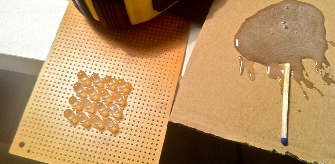
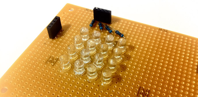
To build a 4x4 common-row cathode matrix you will need 16 LEDs, four resistors, some headers and prototyping board. I started by gluing the leds to prototyping board with epoxy glue. This way it is easier to have LEDs beautifully aligned. When gluing the leds make sure long and short legs are aligned the same way.
When glue is dry it is time to bend and solder. First bend all cathodes to left as close to prototyping board as possible. Solder all cathodes in each row together. When cathodes are ready, bend all anodes. Anodes must not touch cathodes. I used piece of plastic tubing to help bending the anodes to form a bridge above cathodes.
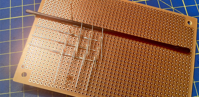
Now solder together all anodes in each row. Solder the headers and connect cathode rows directly to the header.
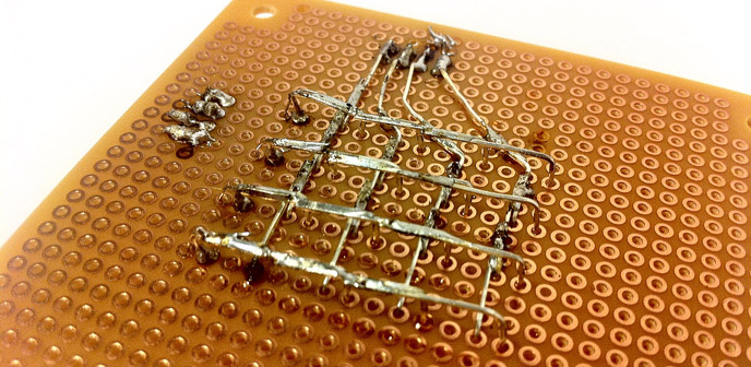
Anode rows are connected to header with current limiting resistors. Value of the resistor depends on the LED used. Check the LED datasheet for forward voltage and current. LED calculator will help you finding out correct resistor. Matrix is now ready for testing.
Addressing Single LED
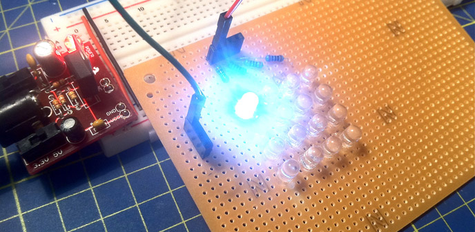
Connecting ground to row A and positive voltage to column 1 will light the top right LED (A,1).
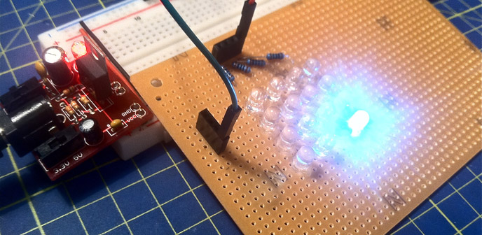
Connecting ground to row D and positive voltage to column 4 will light the bottom down LED (D,4).
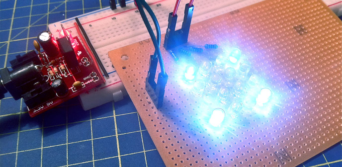
Intuition would say lighting the both (A,1) and (D,4) at the same time is just connecting all the four wires. This is not the case. There are four LEDs which are lit. This is because current is also flowing through (A,4) and (D,1).
Multiplexing and Persistence of Vision
Multiplexing can be used to display arbitrary patterns with led matrices. Multiplexing is sometimes also called scanning. It scans rows (usually from up to down) and lights needed leds only in one row at time. Something like following:
- Start by having everything disconnected.
- Connect positive voltage all the needed columns.
- Connect row to ground. This lights the needed leds in the row.
- Disconnect the row and all columns.
- Do the same steps one by one to all rows and then start from the beginning.
Do this slowly and you would see blinking LED rows. Do it really fast and human eye can see the whole pattern. Phenomenon is called persistence of vision.